
Differences between double-fork, single-fork, and U-shaped brackets for industrial casters
An industrial caster bracket connects the equipment, the wheel axle, and the wheel, and its shape changes the load path and the mounting space. Double-fork, single-fork, and U-shaped brackets are common support methods, and naming may differ among specific products. When comparing them, first mark the mounting location, fork legs, and wheel axle support points on the structure drawing, then examine the material, cross-section, and connection position along the load direction; the name only helps identify the shape.
A double-fork bracket usually places the wheel between the fork legs on both sides, with each end of the wheel axle separately supported. The load is split from the mounting location into the two fork legs, then transmitted to the wheel axle and wheel; after assembly, observe whether the wheel is centered, whether the clearances on both sides are similar, and whether the fork legs are splayed. The plate material, fork spacing, wheel axle, connections, and swivel head together determine its working state, and heavy-duty versions should also be checked item by item along this load path.
A single-fork bracket generally supports the wheel axle from one side of the wheel or from an offset position, leaving the other side open, which can clear equipment components or facilitate disassembly. The load passes concentrated through one side of the bracket, so the cantilever area, the wheel axle root, and the connection region deserve closer observation. During a loaded push test on a sample, if the wheel gradually tilts, axial clearance increases, or it rubs during turning, then the bracket bending, wheel axle fit, and lateral forces should be rechecked.
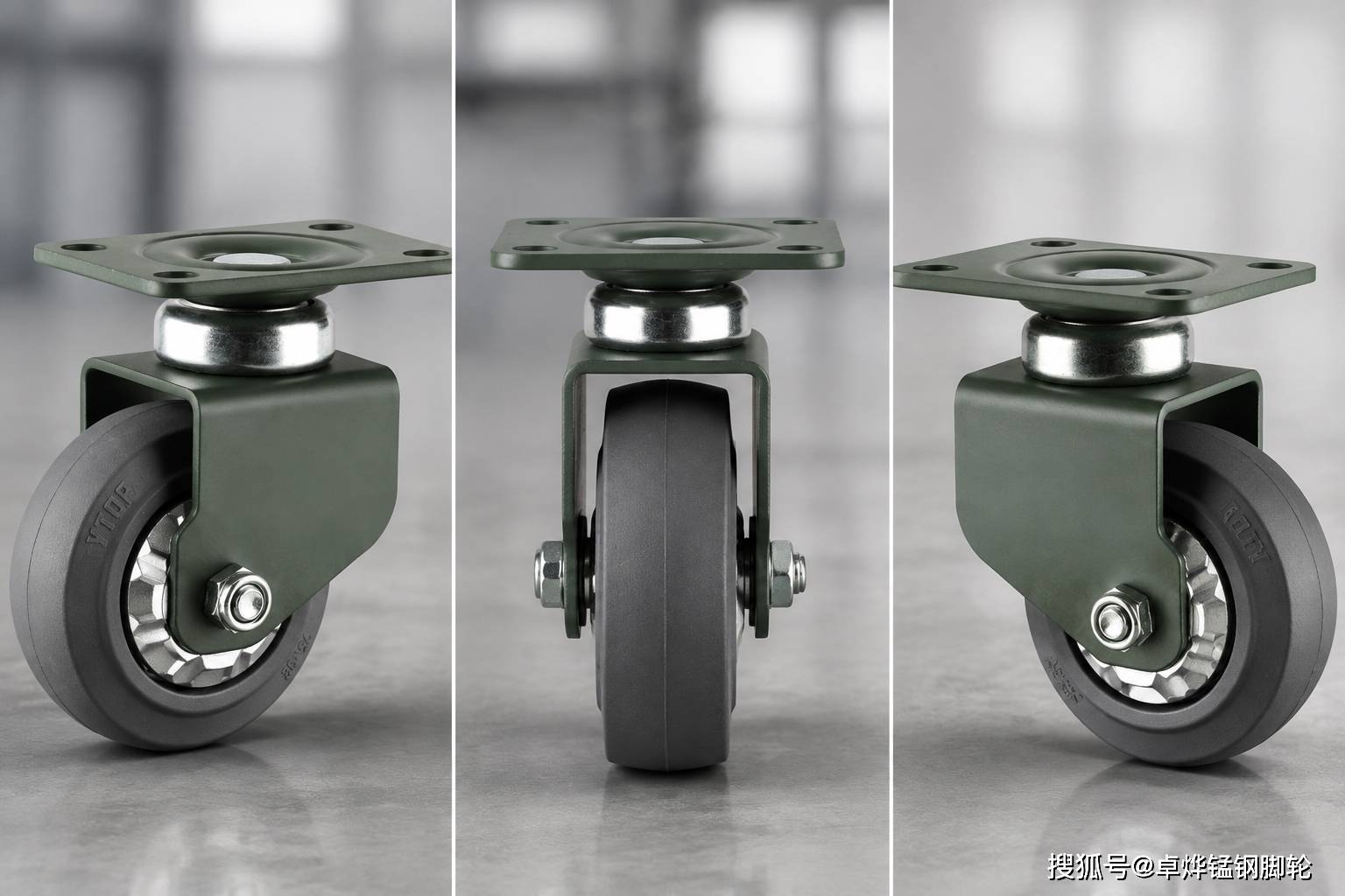
A U-shaped bracket is often formed by a bent part providing support on both sides around the wheel, appearing approximately U-shaped from the front, and similar in appearance to some double-fork designs. During inspection, look for deformation or cracks along the bend radii, both fork legs, and the connection surface, then measure whether the inner width is consistent with the wheel width, spacers, and bearing structure. Different materials, cross-sections, and connection methods produce different load behavior; centering, edge rubbing, and swiveling state during a push test are more intuitive than the name.
The three structures occupy different mounting envelopes. Double-sided support must leave width for the fork legs and the wheel axle ends; a single-fork bracket is open on one side, with the supporting members concentrated on the other side; the inner width of a U-shaped bent part must accommodate the wheel width, spacers, and bearings. When the equipment underside has guards, drive components, or narrow slots, the swivel path can be marked on a sample, turned through the full angle and pushed around a curve, recording the closest positions of the fork legs, wheel axle ends, and pedal to surrounding components.
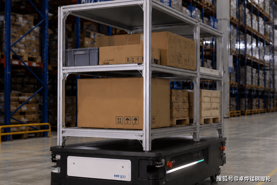
Maintenance inspection also follows the structural path. For a double-fork or U-shaped structure, check the coaxial state of the wheel axle holes on both sides, splaying of the fork legs, and centering of the wheel; for a single-fork structure, focus on deformation at the cantilever, looseness at the connection, and axial clearance. After replacing a wheel, reinstall the original spacers and wheel axle fasteners, turn it unloaded, and then push it under control; if edge rubbing, uneven wear, or brake drag occurs, trace back to the bearing fit and assembly position based on the marks.
When selecting a bracket, list the static load, start-stop and turning forces, floor impact, equipment center of gravity, and mounting interface on the same checklist. Plate thickness, bent cross-section, reinforcement locations, and weld or rivet quality correspond respectively to load-bearing and connection state; powder coating is recorded in the surface inspection column. After the sample is mounted on the cart, the tilting, wobble, rubbing, and continuity of swiveling can help confirm whether these structures match the working conditions.
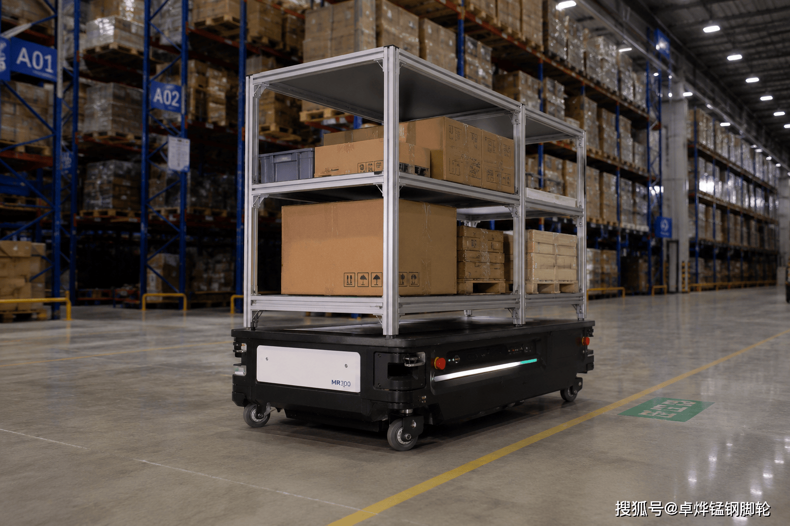
During selection, the equipment underside photos, mounting drawing, and load and swivel envelope can be handed to Zhuoye for checking, and then the support points, fork spacing, wheel axle, and clearance space can be marked on the drawings of the candidate series. After the sample is mounted on the cart, see whether the two sides rub, whether the wheel is centered, and whether a full-angle swivel can avoid the guard plate. Double-fork, single-fork, and U-shaped are only an entry point; only by translating the name back into where the load enters, where the wheel axle is supported, and how much space is left around it does the bracket comparison become practically meaningful.